
Choosing a Mechanical Shaft Seal is not a catalog exercise. It is a decision about fluid, pressure, temperature, speed, and the consequences of leakage. A seal that performs well on clean water may struggle with abrasive slurry or a hot chemical process. Start with the actual duty.
J. F. Flitney, author of the technical reference Mechanical Seal Practice, is a respected source on seal design and application. A useful principle drawn from that field is: “Match the seal to the operating conditions, not just the pump.” This is a practical paraphrase, not a verified direct quotation. It captures a point that is easy to overlook. Small details matter.
Before comparing seal types, record the fluid’s properties, shaft speed, pressure, temperature, and available flush or cooling arrangements. Check the equipment drawing, operating history, and manufacturer’s limits. Then consider materials, seal arrangement, installation space, and maintenance access. For example, a narrow stuffing-box dimension can rule out an otherwise suitable design. So can dry running during startup.
This guide outlines how to assess those factors and discuss them with a qualified supplier. No selection method removes uncertainty. Process data can be incomplete, and real operating conditions may differ from the design sheet. Verify assumptions before ordering. A careful review can reduce premature wear, leakage, and avoidable shutdowns.
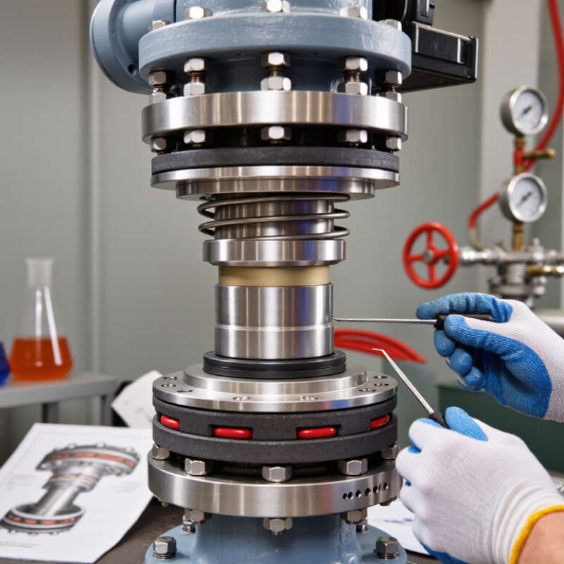
How to Choose a Mechanical Shaft Seal
A mechanical shaft seal controls leakage where a rotating shaft passes through a stationary pump casing. It uses contacting faces, typically made from hard, wear-resistant materials, with secondary seals closing nearby gaps. That matters. The U.S. Department of Energy’s 2006 sourcebook, Improving Pumping System Performance, estimates that pumping systems account for nearly 20% of global electricity demand. It also reports they use 25–50% of energy in some industrial plants. Those figures describe pumping systems, not seal performance, but they show why dependable equipment matters.
Common seal types include pusher and non-pusher designs, balanced and unbalanced face arrangements, and single or dual seals. These categories describe different features, so one seal may fit several labels. Cartridge seals arrive preassembled, which can reduce installation errors; component seals require careful assembly on site. API Standard 682 offers selection guidance for pumps in petroleum, natural gas, and chemical service. In practice, consider pressure, temperature, shaft movement, fluid solids, and the flush or barrier arrangement. A clean, cool liquid differs sharply from an abrasive slurry. The choice is rarely tidy. A seal selected by fluid name alone may still fail early if operating conditions are overlooked.

Start with the fluid, not the seal drawing. Record its composition, viscosity, temperature, pressure, and suspended solids. A warm, clean water service differs sharply from abrasive slurry. Small details matter. Note startup frequency, speed changes, dry-running risk, and whether the pump can cavitate. These conditions shape seal faces, elastomers, and support arrangements.
Check the equipment itself. Measure the seal-chamber dimensions and shaft runout, then confirm available flush connections and cooling capacity. API Standard 682 provides widely used guidance for seal selection and support systems in centrifugal and rotary pumps. Its framework is useful, but the actual operating history matters too. A specification can miss brief pressure spikes or a flush line that clogs during shutdown.
The energy stakes are broader than the seal alone. The U.S. Department of Energy’s 2006 Improving Pumping System Performance sourcebook estimates that pumps use nearly 20% of global electricity; some industrial facilities devote 25–50% of their energy to pumping. That makes reliable operation worth careful attention.
Test the assumptions. If field records are incomplete, say so, and verify conditions with operators before finalizing the selection. A neat datasheet is not the whole story.
How to Choose a Mechanical Shaft Seal
Matching Seal Design and Materials to the Application
A seal that works well in clean water may struggle with hot oil or a slurry carrying fine grit. Start with the actual operating range: pressure, temperature, shaft speed, fluid chemistry, and the number of starts and stops. Include brief upset conditions, not just normal operation. Small details matter.
A single seal may suit a stable, lubricating fluid, while a double arrangement can provide additional control when leakage needs closer management. Abrasive solids may call for a design that keeps particles away from the sealing faces. Face materials also need to suit the fluid and operating conditions. Carbon, silicon carbide, and tungsten carbide each have trade-offs in wear, friction, and compatibility. Elastomers must be checked against the exact fluid and temperature; a generic compatibility label is not enough.
Installation conditions deserve equal attention. Shaft runout, poor alignment, vibration, and dry starts can shorten seal life, even when the materials look right on paper. Check whether the seal will receive adequate lubrication and cooling. This is easy to underestimate. A practical selection review should use process data, maintenance history, and the equipment maker’s tolerances. Some details will remain uncertain until the seal runs under real conditions, so record early leakage, temperature, and vibration rather than assuming the first choice is perfect.
| Application or Service | Main Selection Concern | Typical Seal Design | Common Face-Material Options | Secondary-Seal Options | Practical Selection Guidance |
|---|---|---|---|---|---|
| Clean, cool water | Dry running during startup, poor lubrication, or water containing dissolved minerals | Single seal; balanced or unbalanced design as permitted by pressure and the seal manufacturer’s limits | Carbon against silicon carbide (SiC); SiC against SiC where greater wear resistance is needed | EPDM is often considered for water service; other elastomers may be suitable depending on additives and temperature | Confirm that the seal chamber remains flooded and that the selected elastomer is compatible with treatment chemicals. Avoid operation without adequate liquid at the faces. |
| Abrasive slurry or wastewater with suspended solids | Solids can obstruct the seal faces, cause abrasion, or collect around the springs | Seal arrangement designed for solids service; a flushed, quench, or other auxiliary arrangement may be appropriate | Hard faces such as SiC against SiC are commonly considered for abrasive service | Choose for the liquid chemistry and temperature; EPDM or FKM may be suitable in some services but are not interchangeable | Review solids size, concentration, hardness, and tendency to settle. Consider seal-chamber flushing or a design with reduced exposure of springs to solids. |
| Hot water or condensate | High temperature, flashing, and changes in liquid lubricity | Single balanced seal where required by operating conditions; cooling or circulation may be needed | Carbon against SiC is a common starting point; final choice depends on temperature, pressure, and water chemistry | EPDM can suit many hot-water services; confirm the specific compound’s temperature and chemical limits | Check pressure and temperature at the seal chamber, not only at the pump inlet. Prevent the liquid from vaporizing at the seal faces. |
| Hydrocarbons and lubricating oils | Low lubricity, vaporization, or leakage consequences, depending on the fluid | Single seal for suitable services; dual seal may be selected when leakage control or process containment requires it | Carbon against SiC is commonly used; other face pairs may be selected for specific lubrication and wear conditions | FKM is commonly considered for many oil and hydrocarbon services; compatibility depends on fluid composition and temperature | Verify viscosity, vapor pressure, additives, and the possibility of dry running. Select a balanced design when required by the pressure and operating envelope. |
| Corrosive chemicals, acids, or alkalis | Chemical attack on faces, elastomers, metal parts, or seal hardware | Single or dual seal, depending on toxicity, volatility, leakage limits, and process requirements | SiC is often considered for chemical service, but compatibility must be checked for the exact chemical and conditions | PTFE-based secondary seals, EPDM, FKM, or other materials may be options; suitability is chemical- and temperature-specific | Check concentration, temperature, contaminants, and every wetted component. No single face or elastomer material is compatible with all corrosive chemicals. |
| Toxic, hazardous, or highly volatile fluid | Personnel safety, emissions, and consequences of leakage | Dual pressurized seal with a compatible barrier fluid when required by the risk assessment and system design | Material pair selected for the process fluid and barrier fluid; hard faces may be appropriate where wear resistance is needed | Select all secondary seals for compatibility with both the process fluid and the barrier fluid | A pressurized barrier system maintains barrier-fluid pressure above process pressure at the seal interface. Specify monitoring, support equipment, and leakage-management requirements. |
| Light hydrocarbons or fluids near their boiling point | Flashing at the seal faces and loss of liquid-film lubrication | Balanced seal with suitable flush, cooling, or other engineered support; dual arrangement may be required by the service | Face materials selected for the fluid, pressure, temperature, and lubrication conditions | Choose according to the exact fluid composition and operating temperature | Evaluate seal-chamber pressure and temperature under normal, startup, shutdown, and upset conditions. Maintain adequate liquid at the faces. |
| Low-pressure or vacuum service | Air ingress, face separation, and loss of effective sealing under low pressure | Seal specifically configured and qualified for vacuum or low-pressure operation | Selected for the fluid and the seal’s operating configuration | Choose for fluid compatibility, temperature, and vacuum requirements | Do not assume a standard seal will perform under vacuum. Confirm the pressure range and required auxiliary arrangements with the seal designer. |
Selection note: Treat these pairings as starting points, not universal specifications. Confirm pressure, temperature, shaft speed, fluid composition, solids, startup and upset conditions, and leakage requirements against the seal manufacturer’s limits and applicable engineering standards.
Before choosing a mechanical shaft seal, verify the shaft’s actual dimensions rather than relying only on an old drawing. Measure the sealing area with a micrometer at several points; rotate the shaft to check for wear, taper, or scoring. Small differences matter. A groove beneath the seal can create a leak path, while excessive runout may prevent stable face contact. Record the shaft diameter, sleeve dimensions, available axial space, shoulder locations, and direction of rotation.
Dimensions alone do not confirm fit. Check the seal chamber bore, gland bolt pattern, and working length against the equipment drawing. Confirm that the seal type suits the pump’s speed, pressure, temperature, and fluid; these conditions affect face materials and elastomer selection. If a sleeve or adapter is installed, include it in your measurements because it can change the effective shaft size. Compare readings with the seal’s installation limits, not just its nominal size. If measurements disagree, pause and recheck the setup. It is easy to blame the seal too quickly, especially when a worn sleeve has gone unnoticed.
Compare the measured shaft diameter with common nominal sizes before selecting a seal. Inch values are exact conversions from the metric values, rounded to four decimal places.
A matching nominal diameter is only a starting point. Confirm the shaft tolerance and condition, seal chamber dimensions, available installation space, operating speed, pressure, temperature, and fluid compatibility against the equipment and seal specifications.
A mechanical shaft seal should match the fluid, pressure, temperature, and shaft speed—not just the shaft diameter. Check shaft runout, sleeve condition, and available installation space before ordering. A seal can fit on paper yet fail early when vibration or misalignment is ignored. Small details matter.
Installation quality strongly shapes service life. Keep seal faces clean; a speck of grit can score the polished surfaces. Inspect the shaft for burrs, then lubricate elastomers only as specified for the material and process fluid. Avoid dry starts unless the seal design permits them. Use even pressure when seating components, and verify alignment before reconnecting the coupling. Instructions can feel fussy, but skipping one step is an expensive guess.
Maintenance should follow actual operating conditions, not a calendar alone. Record leakage, temperature, and vibration at consistent intervals; changes from the normal baseline can reveal trouble early. Not always obvious. A small, steady trace may be acceptable for some designs, while sudden leakage needs prompt investigation. Service life varies with fluid cleanliness, operating cycles, and startup habits, so no single replacement interval fits every pump. Inspection data is imperfect; readings may miss wear developing between checks. Use those records alongside shutdown findings when choosing the next seal and planning access for replacement.
