Why Is SMT Assembly Important for PCB Manufacturing?
Smt Assembly is central to modern PCB manufacturing because it places components directly onto the board’s surface, enabling compact layouts and efficient, repeatable production. A pick-and-place head can position tiny resistors and integrated circuits within seconds. Reflow soldering then joins their leads or terminals to prepared pads. The process is fast, but speed alone does not guarantee quality.
Industry demand makes dependable assembly increasingly important. In its Spring 2024 forecast, the World Semiconductor Trade Statistics organization projected global semiconductor sales would reach $611.2 billion in 2024, a 16% increase over 2023. That forecast is not a measure of PCB output. It does, however, show the scale of the component market that manufacturers must support. Each device still depends on sound board design, suitable materials, controlled solder paste, and verified process settings.
Small details matter. A shifted component, uneven paste deposit, or poorly controlled reflow profile can create defects that inspection may catch only after valuable production time has passed. IPC-A-610, a widely used electronics assembly acceptability standard, provides criteria for evaluating finished assemblies. Still, no standard replaces process control or skilled review. Smt Assembly is not a magic fix for every manufacturing challenge; fine-pitch parts and mixed component types can complicate production. This introduction explains why the process matters, where it adds value, and which practical limits manufacturers should consider.
What Surface-Mount Technology Means in PCB Manufacturing
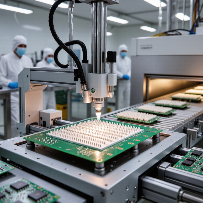
Surface-mount technology, or SMT, places components directly onto conductive pads on a printed circuit board. Unlike traditional through-hole assembly, most SMT parts do not need leads pushed through drilled holes. A stencil spreads solder paste onto the pads; automated placement machines position components, and a reflow oven melts the paste into electrical and mechanical joints. The difference is physical. Tiny resistors may sit beside a processor, while larger connectors still use through-hole mounting on the same board.
The scale of electronics helps explain why this method matters. The World Semiconductor Trade Statistics organization reported worldwide semiconductor sales of $526.8 billion in 2023, reflecting the vast ecosystem of components that circuit-board assemblers must handle. SMT supports dense layouts and repeatable high-volume production, but it is not automatically better for every part. Fine-pitch components can be difficult to inspect, and heat-sensitive parts need careful process control. A misplaced component the size of a grain of rice can disrupt a whole assembly. That detail is easy to underestimate. In practical manufacturing, engineers choose component footprints, solder-paste apertures, and inspection methods together; optimizing only for placement speed can create rework later. The trade-off deserves attention, especially on boards combining surface-mounted parts with through-hole connectors.
How SMT Components Are Placed and Soldered onto a PCB
SMT assembly starts with a clean, flat PCB and a stencil aligned to its copper pads. A printer spreads solder paste through tiny stencil openings, leaving deposits where each component will connect. Too much paste can cause bridges between close pins. Too little may create weak joints. Small variations matter.
A pick-and-place machine uses programmed coordinates and vision cameras to position components. It checks board fiducials, then places resistors, capacitors, and integrated circuits onto the paste. The parts may look still, but the paste holds them only lightly. The board then travels through a reflow oven, where controlled heat melts the solder and forms electrical and mechanical connections. Temperature zones must suit the board and component mix; a profile that works for one design may not work for another.
After cooling, technicians or automated optical systems inspect joints for missing parts, misalignment, solder bridges, and uneven fillets. X-ray inspection can help assess hidden connections beneath some packages. No inspection catches every subtle defect. A slightly shifted component may pass visual checks yet cause trouble during testing, so process records and electrical tests remain important. I would not treat a single successful board as proof that placement and soldering are fully controlled.
How SMT Enables Smaller and More Complex Circuit Boards
Surface-mount technology (SMT) puts components directly onto a PCB’s surface, instead of reserving holes for their leads. That frees space for routing and allows parts on both sides of a board. Tiny resistors and capacitors can sit close to processor pins, shortening connections and helping manage signal paths. The result can be a smaller board with more functions packed into each square centimetre.
Industry data shows why this matters. IDC’s Worldwide Quarterly Mobile Phone Tracker reported 1.24 billion smartphone shipments in 2024, up 6.4% from 2023. WSTS’s Fall 2024 Semiconductor Market Forecast projected global semiconductor sales of about $697 billion in 2025. These figures do not prove that boards are shrinking, but they reflect sustained demand for compact devices and capable chips. Still, SMT alone cannot solve every layout problem. Fine-pitch packages may need high-density interconnects, careful thermal design, and precise inspection. Smaller is not always easier. A crowded board can be harder to repair, and heat has fewer places to go. During design reviews, engineers should check component spacing, solder access, and heat flow—not just the final board outline.
How SMT Improves Manufacturing Speed and Assembly Consistency
Surface-mount technology allows components to be placed directly onto a PCB, often on both sides. Automated machines position tiny resistors and chips from programmed data, while stencil printers apply solder paste to precise pads. The sequence can move quickly. But speed depends on good preparation.
Once a line is calibrated, repeatable placement reduces manual handling and variation between boards. Fiducial marks help machines correct alignment, and controlled reflow profiles form solder joints across many connections at once. That consistency matters. A misplaced component can interrupt later testing, even when the board looks nearly complete. Inspection systems can flag visible placement or solder issues, though they do not replace sound process control.
SMT also supports compact layouts and high-volume production, but each product still needs an appropriate setup. Feeder loading, stencil condition, paste quality, and changeover checks all affect results. A fast line can repeat a bad setup just as efficiently. That is easy to overlook. In practice, manufacturers balance throughput with inspection and process records, then adjust settings when defects appear. The balance is not perfect; unusual board shapes or low-volume runs may need extra handling. Still, consistent methods make production more predictable and help teams trace problems before they spread.
What Factors Limit the Use of SMT in PCB Assembly
Surface-mount technology makes dense, repeatable PCB layouts possible. Components sit directly on copper pads, leaving more room for routing and often reducing assembly time. Yet SMT is not ideal for every part or board. Large connectors, heavy components, or parts exposed to repeated pulling may need through-hole mounting for stronger mechanical support. Not always.
Thermal limits can also narrow the choices. Reflow soldering heats the entire board, so heat-sensitive components must tolerate the selected temperature profile. A board with thick copper, uneven mass, or large thermal planes can heat inconsistently. That may cause weak joints or defects that require careful process adjustment. Tiny, fine-pitch packages bring another challenge: solder bridges and hidden joints can be difficult to inspect or repair.
Cost and production volume matter, too. SMT setup can require stencils, programming, and placement equipment, which may be excessive for a very small prototype run. Mixed-technology boards add handling steps because some parts need hand soldering or a separate process. Designers should check component availability, package dimensions, thermal ratings, and service needs before committing. It is easy to optimize for compactness and overlook how a technician will replace one damaged part later.