
How to Choose Industrial Fabrication Methods in 2026?
Choosing the right Industrial fabrication methods in 2026 is no longer a simple cost exercise. Factories now balance material behavior, automation, energy use, delivery risk, and workforce capability. A stainless steel enclosure may need laser cutting, press braking, and controlled welding. A heavy structural frame may favor sawing, robotic welding, and stress relief. The best answer depends on tolerances, production volume, geometry, and the consequences of failure.
Small details matter. A sharp internal corner can increase machining time. A thin wall can distort during welding. These realities often expose weaknesses in early estimates. This guide compares established and emerging processes through a practical engineering lens. It considers CNC machining, sheet metal forming, additive manufacturing, casting, forging, and hybrid production. Evidence should come from qualified suppliers, documented trials, inspection records, and repeatable performance data. Certifications help, but they do not replace process knowledge or physical testing. Readers should examine surface finish, dimensional stability, tooling investment, repairability, and total lifecycle cost. A cheaper quotation may hide rework, rejected parts, or long maintenance delays. That lesson is easy to miss. Technology forecasts can also be overconfident. Not every factory needs the newest machine. In 2026, responsible selection means matching proven capability with measurable business needs. The final decision should remain open to review after prototypes, production feedback, and supplier audits.
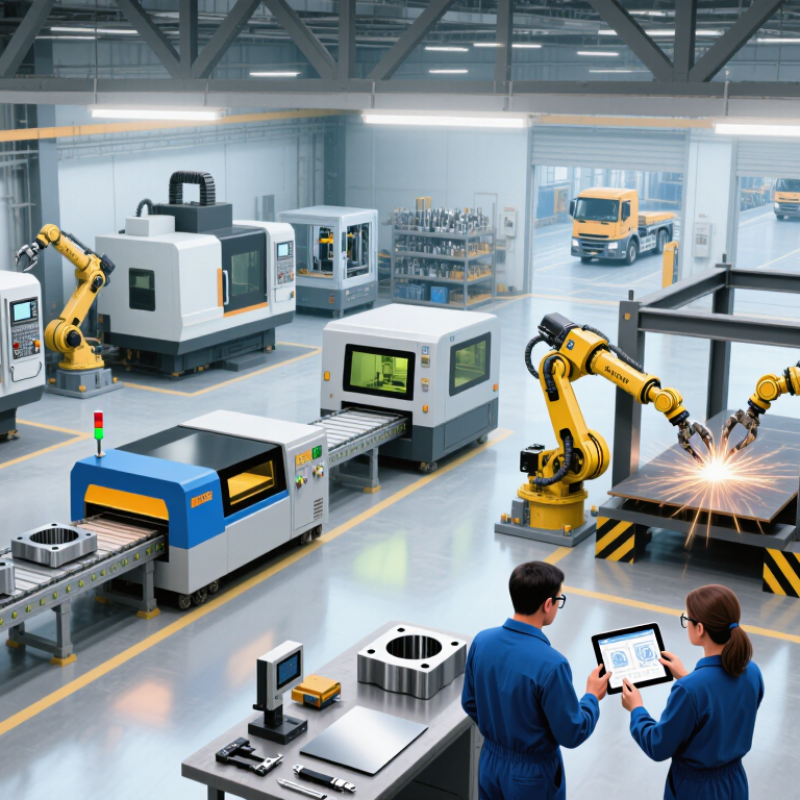
Define Part Requirements: Material, Tolerance, Volume, and Lead Time
Choosing an industrial fabrication method in 2026 starts with a measurable part definition, not a machine preference. Record the material grade, wall thickness, surface finish, tolerance zones, volume, and required delivery date. A stainless-steel bracket and a polymer enclosure may share similar geometry, but they rarely need the same process. Material behavior matters. Heat can warp thin sections. Fibers can weaken printed corners. Note the failure you cannot accept.
Tolerance should support function, not habit. A 0.02 mm callout on every surface can increase inspection time and scrap. Identify datum features, mating holes, sealing faces, and cosmetic areas. Separate critical tolerances from ordinary ones. Ask for a gauge plan before production begins. It exposes vague drawings early. I have seen a part pass dimensional checks but fail assembly because its reference surface was poorly defined. That mistake was technical, not dramatic.
Volume and lead time change the economics. One prototype may suit CNC machining, additive fabrication, or soft tooling. Thousands of parts may favor stamping, molding, or automated cutting. Short deadlines can justify a flexible process, but confirm material availability and post-processing capacity. Leave time for first-article inspection. It is often overlooked. Recheck the plan when demand changes; a process chosen for 30 parts can become wasteful at 3,000. Forecasts are imperfect. Build a decision table, document assumptions, and challenge them before releasing the job.
How to Choose Industrial Fabrication Methods in 2026? - Define Part Requirements: Material, Tolerance, Volume, and Lead Time
| Fabrication Method | Suitable Materials | Typical Part Size | Typical Tolerance | Economic Volume | Typical Lead Time | Best Use Case |
|---|---|---|---|---|---|---|
| CNC Milling and Turning | Aluminum, steel, stainless steel, brass, titanium, engineering plastics | Small to medium prismatic or rotational parts | About ±0.01–0.05 mm for standard features; tighter tolerances may require special controls | 1–1,000 parts; suitable for prototypes and low-to-medium production | 3–20 working days, depending on complexity, material, and finishing | Complex geometries, functional prototypes, close-fit components, and low-volume production |
| Laser Cutting | Carbon steel, stainless steel, aluminum, copper, brass, and some non-metal sheets | Flat sheet profiles; thickness commonly ranges from thin sheet to approximately 20–25 mm for steel, depending on equipment | About ±0.05–0.20 mm for many sheet-metal applications | 1–10,000 parts; efficient for prototypes and repeated flat patterns | 1–10 working days | Fast production of accurate 2D profiles, brackets, panels, and nested sheet parts |
| Waterjet Cutting | Steel, stainless steel, aluminum, stone, glass, composites, rubber, and heat-sensitive materials | Thin to very thick plate and large-format sheet | About ±0.10–0.25 mm; accuracy varies with thickness, taper control, and cutting speed | 1–1,000 parts; particularly useful for low-volume and thick-material work | 3–15 working days | Thick, reflective, laminated, or heat-sensitive materials where a heat-affected zone must be avoided |
| Press Brake Forming | Mild steel, stainless steel, aluminum, and other ductile sheet metals | Flat blanks formed into channels, angles, boxes, and enclosures | Typically ±0.5–1.0° for bends; linear dimensions commonly about ±0.10–0.50 mm | 10–10,000 parts; economical when tooling requirements are limited | 2–12 working days, including setup and first-article checks | Enclosures, frames, mounting brackets, cabinets, and structural sheet-metal components |
| Metal Stamping | Low-carbon steel, stainless steel, aluminum, copper, brass, and other coil-fed sheet metals | Small to medium repeated parts made from sheet or coil | About ±0.05–0.25 mm, depending on material, feature size, and tooling | Usually 10,000–1,000,000+ parts | 4–16 weeks initially because of die design and manufacture; repeat runs are faster | High-volume parts requiring fast cycle times, repeatability, and low unit cost |
| Injection Molding | Thermoplastics such as ABS, PC, nylon, polypropylene, POM, and glass-filled polymers | Small to medium complex plastic parts with ribs, bosses, clips, or snap-fits | About ±0.10–0.30 mm for many dimensions; shrinkage and material behavior affect results | Typically 1,000–1,000,000+ parts | 4–12 weeks for initial tooling and validation; production cycles are often seconds to minutes | High-volume plastic housings, consumer components, medical-device parts, and repeatable molded products |
| Additive Manufacturing | Photopolymers, nylon, TPU, metal powders, and selected high-performance polymers | Small to medium complex parts; build volume depends on the selected process | About ±0.10–0.30 mm for many polymer processes; post-processing may improve critical features | 1–100 parts; useful for design validation and customized production | 1–10 working days for many polymer parts; metal parts may require longer processing and finishing | Highly complex geometries, lightweight structures, customized parts, and tooling aids |
| Fabrication Welding and Assembly | Carbon steel, stainless steel, aluminum, and compatible structural metals | Medium to large frames, vessels, guards, platforms, and welded assemblies | Typically ±1–3 mm for fabricated assemblies; machined interfaces may require secondary operations | 1–500 assemblies; practical for customized and low-volume structures | 5–30 working days, depending on size, inspection, finishing, and assembly content | Large structural products, custom frames, brackets, guards, skids, and assemblies too large for one-piece machining |
Related Posts
-
China Top 10 Precision Metal Cutting Technologies and Innovations?
-
How to Choose the Best Industrial Welding Solutions for Your Business?
-
2026 How to Choose the Best Industrial Welding Solutions for Your Needs?
-

China Top Engineering Fabrication Solutions for Modern Industries?
-
China Top 10 Metal Fabrication Processes Manufacturers?
-
What Is Modern Metal Forming and How Does It Work?